Equipment configuration
- Create devices
- Device parameters
- MODBUS devices
- MODBUS register addressing
- IEC 60870-5 devices
- IEC 61850 devices
- Translation status
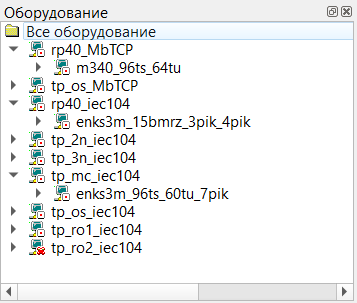
The equipment window can be opened from the main menu with Further -> Equipment.
Create devices
IEC 60870-5 directions can be added from the IEC subsystem context menu, for example with Create -> IEC-101 direction or Create -> IEC-104 direction.
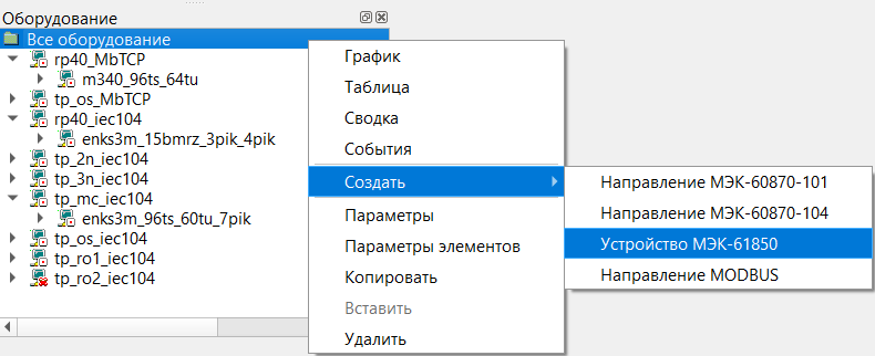
An IEC 60870-5 device can then be added from the direction’s context menu with Create -> Device.
Device parameters
To edit an element’s parameters, open the element context menu and choose Parameters.
MODBUS devices
Supported MODBUS function codes are described in Protocols.
MODBUS direction parameter
- Request delay, ms
- An artificial delay between the response and the next request. This is useful for serial devices that switch slowly between transmit and receive modes.
MODBUS device parameters
- Pause duration, ms
- If several devices are polled cyclically and one device stops responding, polling of that device can be suspended for a while so the other devices can still be queried on time.
- Retry count
- The maximum number of repeated requests when the device does not respond.
- Response timeout
- The maximum wait time for a device response before retrying the request.
MODBUS register addressing
Each MODBUS register is 16 bits wide and is treated as a single word. Each word contains two bytes, Hi and Lo, stored in direct order: [Hi][Lo].
Two MODBUS registers form a 32-bit double word. Four MODBUS registers form a 64-bit value.
Examples:
- single word:
0x10DE - double word:
0x10DE34A8
The protocol uses four logical register groups:
| Register number (dec) | Register address (hex) | Register type | Command | Access |
|---|---|---|---|---|
1-9999 | 0x0000-0x270F | Coils | 0x01/0x05(0x0F) | Read/write |
10001-19999 | 0x0000-0x270F | Discrete Inputs | 0x02 | Read |
30001-39999 | 0x0000-0x270F | Input Registers | 0x04 | Read |
40001-49999 | 0x0000-0x270F | Holding Registers | 0x03/0x06(0x10) | Read/write |
The decimal register number is not the same as the hexadecimal address carried in MODBUS frames. The difference between them is the group offset.
Depending on the register type, MODBUS values can be interpreted as:
BOOLINT8/UINT8INT16/UINT16INT32/UINT32FLOATDOUBLE
Full MODBUS channel-address format
The full format contains one required field and several optional ones:
[type_data[count]:]NUMBER[:bit[+bitcount]][;swapbytes]
Fields:
type_datais one ofBOOL,INT8,UINT8,INT16,UINT16,INT32,UINT32,FLOAT,DOUBLEcountexplicitly sets the number of registers to readNUMBERis the decimal register numberbitis the first bit to mask, numbered from 1 to 16bitcountreads several bits starting atbit;swapbytesswapsHiandLobytes inside a 16-bit word;swapwordsswaps the 16-bit words inside a 32-bit word
Typical examples include:
FLOAT:30001INT16:41105;swapbytesUINT32:41105;swapwordsUINT16:30001:1+7UINT16:30001:9+7BOOL:40003:51100013000140001HOLDREG:FLOAT:10001
Short MODBUS channel-address format
The short format uses the absolute decimal MODBUS register address instead of the logical register number:
TYPE_REGISTER:TYPE_DATA:ADDR
Fields:
TYPE_REGISTERis one ofCOIL,DISCINPUT,INPUTREG,HOLDREGTYPE_DATAis one of the supported data typesADDRis the absolute decimal register address
This format is used when the actual hexadecimal register address is higher than 0x270F.
Examples:
HOLDREG:FLOAT:10001INPUTREG:FLOAT:10001HOLDREG:INT32:10001INPUTREG:UINT32:10001HOLDREG:DOUBLE:10001
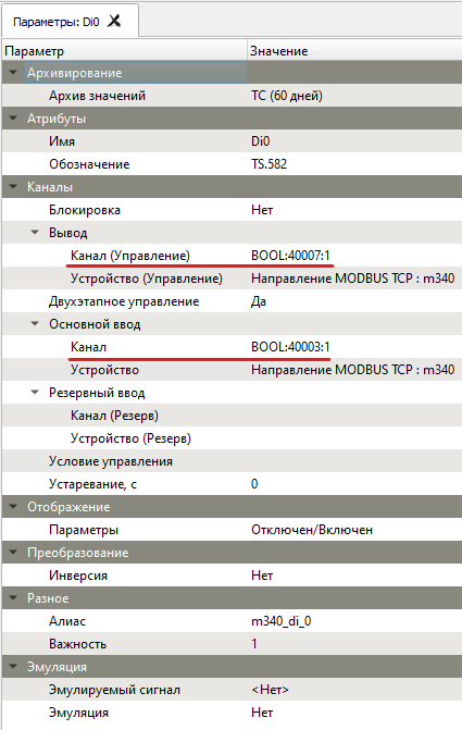
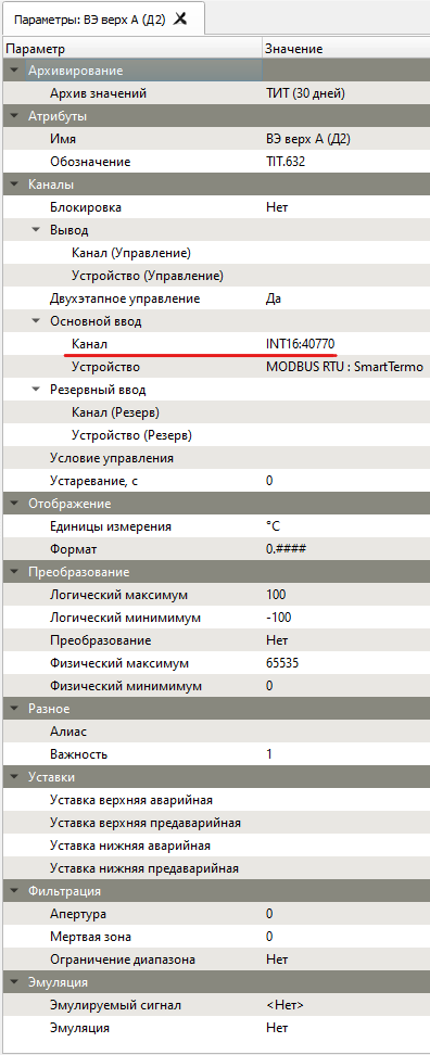
The two parameter screenshots below show where these MODBUS channel definitions are entered for discrete and measured objects:
IEC 60870-5 devices
The supported IEC 60870-5 ASDU identifiers are described in the Protocols page.
IEC 60870-5 direction parameters
- Event archive
- Selects the archive used to store network traffic for later analysis and saving to a text log file.
- Anonymous mode
- Switches the system from balanced mode to unbalanced mode, where the device establishes communication itself and explicit `STARTDT ACT` commands are not required after the link is opened.
- Send window (K)
- Maximum number of transmitted ASDUs before acknowledgement is required.
- Receive window (W)
- Number of received ASDUs after which an acknowledgement is sent.
- Retry count
- Maximum number of retries before communication loss is reported.
- Standard IEC 60870-5 field sizes | Field size, bytes | 104 | 101 | |:---|:---:|:---:| | Information-object address | 3 | 2 | | Device address (common ASDU address) | 2 | 1 | | Cause of transmission | 2 | 1 |
- Operation timeout, s
- Timeout for commands such as control operations and general interrogation.
- Transmission timeout (T1), s
- Time allowed for a response or ASDU delivery acknowledgement.
- Acknowledgement timeout, s
- Time allowed for command completion acknowledgement such as `ACTIVATION TERMINATION`.
- Receive timeout (T2), s
- Time before a receive acknowledgement is sent when no further data arrives. `T2` must be smaller than `T1`.
- Idle timeout (T3), s
- Time before a test frame is sent on an idle connection.
- Connection timeout (T0), s
- Time allowed to establish the connection.
- Transport
- Physical-transport settings for the device channel: 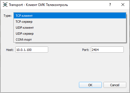
IEC 60870-5 device parameters
- Event archive
- Selects the archive used to store traffic for one specific device.
- Address
- The device common address carried in the ASDU frame.
- Link address
- An additional link-layer address for the device.
- UTC time
- Selects UTC or local time for timestamps.
- Group interrogation periods 1...16, s
- Per-group interrogation periods using the standard general interrogation grouping model.
- General interrogation period, s
- How often `C_IC_NA_1` is sent. A value of `0` means it is sent only once after connection establishment.
- Clock synchronization period, s
- How often `C_CS_NA_1` is sent. A value of `0` means it is sent only once after the connection is established.
- General interrogation on startup
- If disabled, no general interrogation is sent after the connection is opened.
- Clock synchronization on startup
- If disabled, no clock synchronization is sent after the connection is opened.
IEC 61850 devices
The IEC 61850 model can be browsed directly. Any model node can expose its bindable address through the Parameters command in the context menu.
Server objects can also be created by dragging IEC 61850 model objects into an object group. Dragging a full functional-constraint group creates all objects from that group. Dragging a model object onto an existing SCADA object updates the existing binding.
Translation status
This English page is now a substantially fuller engineering reference. The Russian page still remains the fullest source for low-level device details.