Data-item configuration
- Control conditions
- Transformations and formulas
- Creating objects
- Deleting, copying, and moving objects
- Object parameters
- Translation status
Only system administrators and SCADA engineers can create, configure, delete, copy, or move data items and groups.
Each data item can use up to two data sources for hot standby. If the primary source loses validity, the system switches to the backup source automatically and switches back when the primary source recovers.
Each data item can also define one control channel. The control channel may even be the same exchange channel used as the source of the item’s data.
Control conditions
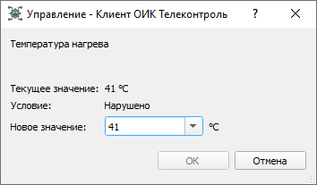
A control channel can include a logical control condition. When the condition is true, control is enabled:
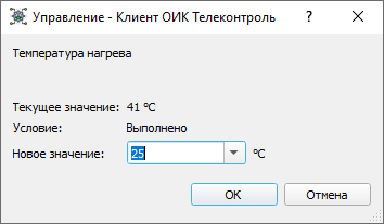
Otherwise, control is blocked:
Transformations and formulas
Incoming values can be:
- inverted for discrete objects
- transformed by a linear scale for measured values
- calculated using a formula
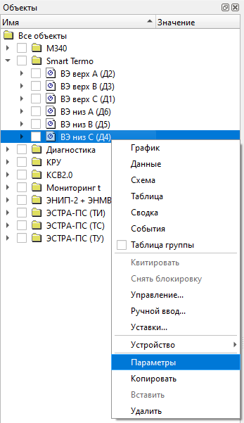
Object configuration is edited through either Parameters for a single object or Element parameters for an object group.
Creating objects
Objects can be created only inside an object group, and groups can be nested inside other groups.
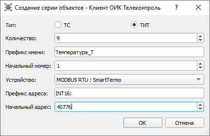
Single objects or object series are created through the Create menu:
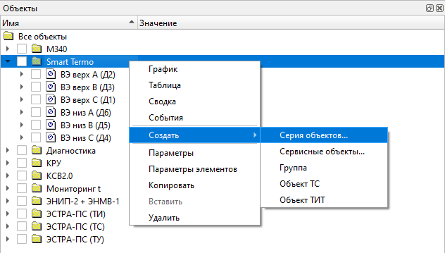
When creating an object series, select the object type and set the initial parameters:
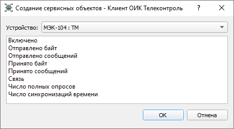
Service objects can also be created for a specific device:
Deleting, copying, and moving objects
Objects and groups can be deleted through the Delete menu:
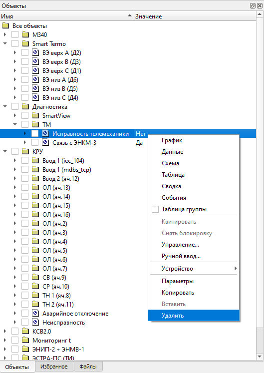
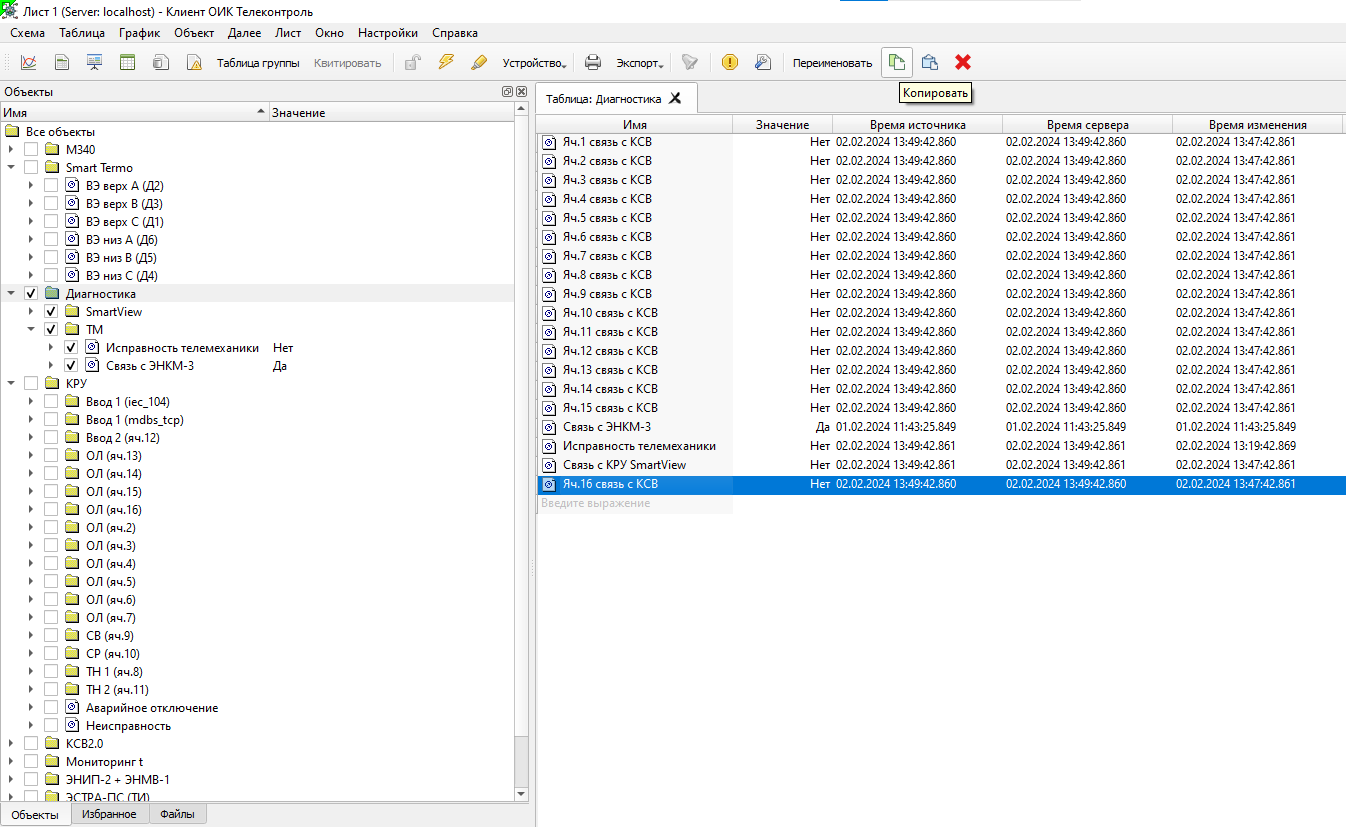
Copying is available through the Copy commands:
Objects and groups can also be dragged inside the object tree.
Object parameters
Measured-object parameters are configured in the object properties window:
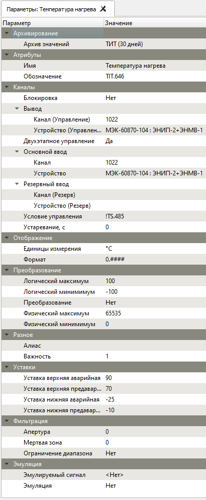
The main parameter groups are:
- Value archive
- Defines the historical retention depth in days and selects the archive where object values are stored for later analysis in graphs, summaries, and the event journal.
- Name
- The display name used everywhere in the system. Names do not have to be unique; full object identification is based on the full path through the parent groups.
- Control channel
- The channel address used for a control command in the protocol format required by the selected device.
- Control device
- Selects the device used as the control-data source for remote commands.
- Two-stage control
- Enables the IEC 60870 two-stage control workflow `SELECT/EXECUTE`. If disabled, the command is executed in a single stage.
- Channel
- Defines either the information-object address in the selected protocol format or a calculated [formula](/scada/en/formulas/) when no device is selected.
- Device
- Selects the primary source device. If no device is selected, the channel field is interpreted as a formula.
- Backup channel
- Defines the information channel or service object for the backup data source.
- Backup device
- Selects the backup source device.
- Control condition
- A logical expression that enables or blocks control. It usually references discrete-object aliases or their internal object numbers.
- Stale timeout, s
- If the value is not updated within this interval, it is marked as stale.
- Display parameters
- For discrete objects, selects the display format used in the UI. The available formats can be managed from `Further -> Formats`.
- Inversion
- Used only for discrete objects to invert the received state.
- Transformation
- For measured values, defines how incoming data is processed:
- Linear
- Applies offset and scale transformation.
- None
- Disables transformation.
- Logical minimum and maximum
- Define the logical value range and the Y-axis range used by graphs.
- Physical minimum and maximum
- Define the physical value range used in linear scaling.
- Alias
- A unique system-wide alias used in formulas, logical expressions, tables, graphs, and schematic bindings. Aliases may contain Cyrillic or Latin letters and digits, but no spaces, and must be no longer than 50 characters.
- Importance
- A decimal value from `0` to `1,000,000,000` used for event coloring and filtering in the event journal and current-event panel.
- Acknowledged events are typically shown with these severity zones: * importance `< 60`: black text on white background * importance `< 80`: black text on yellow background * importance `> 80`: black text on red background
- Unacknowledged events are shown with black text on a green background until acknowledgement.
- Range limiting
- Clamps the value to the logical range.
- Display
- Controls how a measured value is formatted:
- Engineering units
- The unit suffix shown after the value.
- Format
- The number of decimal places.
- Emulation
- Enables signal emulation. The emulation type is selected from the configured list of simulated signals under `Further -> Simulated signals`.
Translation status
This English page is now a substantially fuller engineering reference. The Russian page still remains the fullest low-level source.